Gauging stations are installed for carrying out of regular observation on rivers when studying its hydrologic regime. The water level and flow rate observation carried out by water level gauges, which are elements of gauging stations, is essential for irrigation and drainage purposes. Simple water level gauges are divided into two types: piled and rack-based.
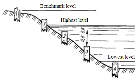
Piled water level gauges are installed at the rectilinear river section, where there is no backwater effect caused by any obstacle slowing down the river course. If such a gauge is installed perpendicular to the water course, a section line is marked according to which a benchmark (on the flood-free part of the bank) and piles are installed.
The piles are to be set on the river bank and bed in line. The piles get numbered beginning from the benchmark. Their number depends on the bank steepness and water level fluctuation amplitude. Elevation of the pile top above each another should come to 0.6-0.8 m. The first pile is installed higher than the maximum water level by 0.3-0.5 m, the last should be lower than the minimum level by 0.5 m.

Pile water level gauge: 1-4 are pile numbers
Before the installation of gauges, the location of the highest and lowest levels is commonly found out by conducting an opinion poll among the local population.
Metal piles are used, which are produced in quantity by plants, or wooden ones made from coniferous wood (larch is preferable) or hard-wooded broadleaved species (oak is preferable). The pile diameter is to be 15-20 cm. A metal ring is put on the pile top before driving it in. After the pile is driven in, it is smoothly sawn and a clout nail is hammered in its center, on which a rod is placed when measuring water level. The pile top and benchmark are linked by leveling off.
A rack-based water level gauge is placed on river sections with stable steep banks (with securing it in place is needed), on embankments, bridge footings as a rule at relatively little (up to 5 m) amplitude of annual water level fluctuation. Water level is measured by a gauging-rod which is the main component of the water-level gauge. Water gauging-rods are made from wooden (from hardwood) or metal materials. In outward appearance, the rod somewhat resembles a leveling rod. Its length if 2 m (if needed, two rods are to be installed), width is 13 cm, thickness is 2.5 cm. The rod is divided into sections with scale intervals of 2 cm, with numbering on the right and left sides of the face side. At water-level gauges, they measure water level on a daily basis (at 8 a.m. and at 8 p.m.).
Water-level gauges with recorders (limnographs) are used at special objects under observation. Generally, a coastal self-recording water-level gauge is used.

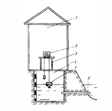
Coastal recorder installation diagram:
1 – booth; 2 – recorder; 3 – table; 4 – well; 5 – float; 6 – connecting pipe
A device for measuring water level by recorders includes a limnograph booth 1, well 4 connected with pipe 6 with watercourse, and recorder 2 placed on Table 3. The well is made closed. The well water is kept at the watercourse level (river, stream, etc.) by means of a connection pipe. The pipe is laid lower than the minimum water elevation in the watercourse. The well bottom is set a little deeper than the bottom surface of the connection pipe. To protect the well against freezing, the well is covered with a solid double cover plate, by locating the lower cover plate at 0.3-0.5 m above the soil surface.
Recorders are used to record water level. They are designed by the State Hydrological Institute. At present, “Valday” type recorders are used. They operate in water recording mode for 12 and 24 hours, and of GR-38 [in Russian] ГР-38) of long-term action. A timing device therein allows keeping records during 8, 16, or 32 days.
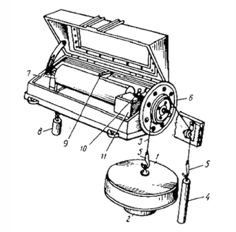
“Valday” recorders operate as follows. The float, moving with changing the water level in the well, through block 6 imparts rotary motion to cylinder 7 which a special ruled tape is fixed onto. Weight 8 moves the carriage with stylus 9 by means of a guide rope. When rotating, the movable stylus is making records of the changes in water level. Having taken the tape from the recorder and having it processed, the mean water level is determined for each observation day.

General view of a “Valday” recorder:
1 – float with a weight; 2, 3 – rope of the float-counterbalance system; 4 - counterbalance; 5 - hooks; 6 – floating block; 7 - cylinder; 8 – weight with rope; 9 – carriage with stylus; 10 – head of clock winding mechanism; 11 - clock mechanism
Source: Babikov, B.V. Hydrotechnical reclamation. Textbook for higher educational institutions,
3rd edition, revised and enlarged. Saint Petersburg, LTA, 2002
Technical standards