To the beginning of the section
The lift irrigation method is used both for watering of a certain area as a whole and for water application to particular elevated sites in the area of gravity irrigation (at that water is lifted from river or from irrigation canals). Such combination of gravity and lift irrigation is rather reasonable in many cases.
Irrigation with which water is supplied to the system by water-lifting devices is called pumping/mechanical/lift irrigation (by means mechanical water-lifting devices).
Head/diversion structure is a water-lifting device that supplies water by means of pumps to an irrigated area through a pressure pipeline. Water from a source is lifted up to the highest elevation of the entire irrigated area or its certain zones, and from there it is distributed by gravity canals or pressure pipelines.
Lift irrigation is used both for water application by gravity to the entire area and particular elevated sites.
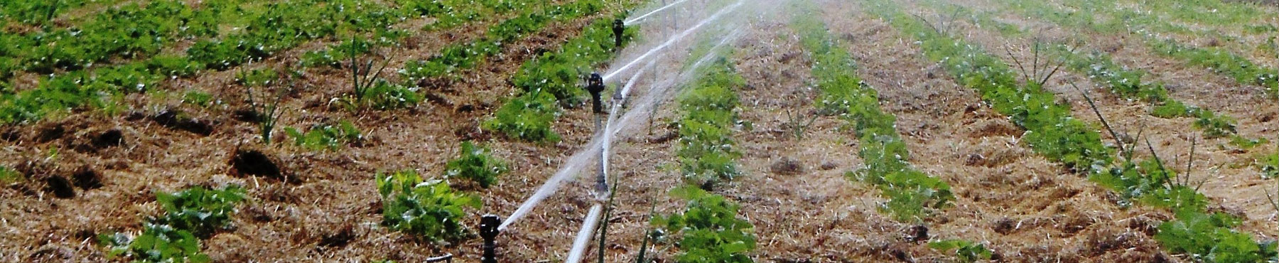
At sprinkling irrigation, pumping stations not only supply water at a target rate, but also produce required water head.
A drawback of lift irrigation is a need for complex pumping and power equipment, power supply, and high operating costs. All these factors raise the cost of water supply to fields.
However, in spite of high operating costs and its high cost, the lift irrigation method is often economically sound and profitable.
With lift irrigation, the routes of main irrigation canals and pumping stations can be arranged according to four layouts.
First layout. The entire irrigated area is located within a single zone, irrigated from one main irrigation canal that receives water from a pumping station through a pressure pipeline.
Second layout. An irrigated area similar to that in the first layout, but water is supplied not from one canal, but from several canals. The area is divided into several water-lifting zones; each zone is served by an assigned main head canal that traces through highest elevations of its zone and receives water by special pressure pipelines, but from the common on-shore pumping station.
Third layout. An irrigated area is divided into zones as well, but each zone canal is fed by independent pumping stations that supply water in succession from downstream to upstream zones.
The first on-shore pumping station PS-1 supplies water to the elevation of the first zone at a rate sufficient to water all the three zones. The station PS-2 supplies water to the elevation of the second zone at a rate sufficient to water the second and third zones; the station PS-3 supplies water to the highest elevations of the third zone.
Fourth layout. An irrigated area is divided into zones; at that each zone has its own water feeding source independent of other zones; every zone is supplied by an independent on-shore pumping station. Such a layout is employed when using mobile pumping stations.
Proper solution of a lift irrigation problem depends on determining of the number of pumping zones. At that, division of the irrigated area into separate zones is significant. The capacity of pumping stations lowers with increasing number of pumping zones, and vice-versa. Therefore, at the designing stage an optimal combination of the arrangement of canals and pumping stations should be found, which would result in lowest costs of building and operation of pumping stations and main canals.
When designing pumping stations, they assess the expediency of the use of one heavy-capacity and several lower-capacity water-lifting devices for irrigation of a certain area.
Stationary and mobile pumping stations and plants are applied for lift irrigation. Stationary pumping stations are more widely used than mobile ones. Stationary stations include the following complex of hydraulic facilities: water intake structure; supply canal; reception basin, station building; pressure pipelines; and overhead reception basin.
Source: Agricultural hydrotechnical reclamation / Bogushevskiy, А.А., Folovanov, А.I, Kutergin, V.А. et al.; Edited by Markov, E.S. – Moscow, “Kolos” Publishing House, 1981 (in Russian)