The irrigation system represents irrigation and drainage system designed for land reclamation. The principal engineering problem of the irrigation system consists in withdrawing water from an irrigation source, delivering it to irrigated land in due time and in required amount, distributing it among individual farms and crop-rotation fields, and providing soil moisture needed for plants on fields.
Among irrigation system components are:
• Irrigation source;
• Head water intake structure;
• Irrigation network;
• Water-collecting & escape network and collector & drainage network;
• Hydraulic facilities in the network;
• Forest belts and road network;
• Irrigated lands with inter-farm and on-farm planning of the territory.
Hence, the irrigation system of continuous flow irrigation represents a complex composed of irrigated lands, irrigation source, and various structures on those for fundamental improvement of adverse natural conditions and enhancement of soil fertility with the view of gaining heavy crop yields with the most efficient use of land and water resources and without having detrimental effects on surrounding lands.
Water sources for irrigation can be represented by: rivers in their natural or regulated condition; lakes; local surface runoff inflowing to ponds; groundwater; and reused commercial, household, and waste waters of the system.
The basic requirement to the irrigation sources is to supply required volume and proper quality of water. Water quality is determined by hydrological and water-management design. The water source can be located close to the irrigated land and advisably at higher elevation than that land (so that to ensure gravity water supply).
When designing the irrigation system, it is necessary to know the hydrological characteristics of the irrigation source, hydrogeology, and land form. Being aware of these features, one can determine the following: possible irrigated area; necessity to regulate the irrigation source; need for water clarification; pattern of water withdrawal and water supply to the irrigated land.
The irrigation source is to completely satisfy water requirement throughout the irrigation period. Harmonization of the irrigation source regime with the irrigation regime is provided as follows: 1 – by regulating the water source; 2 – by adapting the irrigation regime to the water source regime; 3 – by simultaneously regulating the water source and the irrigation regime.
Irrigation water quality is assessed based on agronomic (soil fertility, prevention of salinization, alkalinization, and sodium formation processes, productivity, product quality and storageability), technical (content of microelements, radioactive substances, pH, etc.), and environmental (content of the causative agents of diseases that are hazardous from the epidemiological point of view, quantity of bacteria) criteria.
The head water intake structure is used for water withdrawal from an irrigation source and delivery to an irrigation network.
There are three types of water withdrawal/intake:
• river-canal (damless) intake;
• dam intake;
• water-lifting intake.
According to the way of water withdrawal from an irrigation source, irrigation systems are divided into gravity and water-lifting types.
According to its function, the irrigation system is divided into two parts: conduit and regulation networks.
The conduit network is built as permanent. Its purpose covers water transport from an irrigation source to irrigated lands and water distribution between particular farms, crop-rotation plots and fields within the irrigated lands’ boundaries.
The conduit network includes: the main canal MK and its branches 1-МК and 2-МК; inter-farm and farm distributors of different orders 1-1.К, 1-2.К, 1-2.1.К, 1-2.1.1.К; and on-farm distributors 1-1.К 1, 1-1.К 1.1.
The main canal and its branches deliver water from a water-intake structure to different-order distributors.
Inter-farm distributors deliver water from the main canal to several farms, while farm distributors to a single farm.
On-farm irrigation canals distribute water among production sites, crop-rotation plots, and irrigated fields within a farm. Lowest-order on-farm distributors that deliver water to irrigated plots are called delivery ditches.
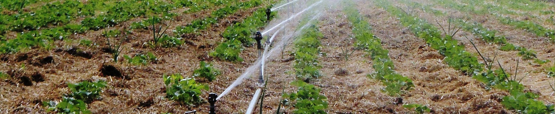
The purpose of the regulation network is to distribute water over the field and transform water from the state of flow into the state of soil moisture.
At surface irrigation, the regulation network is composed of temporary ditches, field head ditches and furrow ditches, irrigation pipes, irrigating machines, irrigation ditches, furrows, and checks; at sprinkling irrigation, it is composed of sprinkling machines (sprinklers) and pipelines; at subsoil irrigation, it is composed of soil moisteners.
In order to exclude restricting the conditions for mechanical operations at agricultural fields, the regulation network is made temporary, portable or mobile, or fixed, i.e. put at a certain depth in the ground.
According to its design, the irrigation network can be broken down into three types as follows:
• open type consisting of unlined (earth) canals or lined canals if it is needed to reduce seepage or rise the flow velocity, or of flumes used in complex topographical and geological conditions;
• closed type consisting of pressure and free-flow pipelines laid in the ground; on the surface, water is supplied by means of hydrants;
• mixed type, in which the major large canals are made open, the major network is closed, or water from a water intake structure to a farm is delivered through pipes, and the on-farm network is made in the form of open canals and pipelines.
The water-collecting & escape network is meant for collecting and diverting excessive surface water and discharging water from irrigation canals. It consists of:
• emergency water removal and tail escapes,
• water-collecting canals of different orders, and
• interception drains that protect irrigated lands from inflowing surface water from upper areas.
The drainage network serves for diverting excessive ground water from the area commanded by the respective irrigation network. It consists of inter-farm and on-farm collectors and drains.
The irrigation network is equipped with hydraulic structures. Flow regulators are installed to control water level and flow rate in canals; water-conveying facilities (aqueducts, inverted siphons, tunnels) are installed to transport water over/through man-made and natural obstacles; and check drops and inclined drop structures are installed to connect lower and upper reaches. The hydraulic structures are equipped with water metering, water level and flow rate controlling automatic devices as well as centralized remote monitoring and control devices. Network of observation wells is arranged to monitor groundwater level at an irrigated area.
Roads are designed for servicing the system, for agricultural machines to travel, for supplying seed grains, moving out crops. Field roads are built in order to connect with each field: on-farm ones are built for connecting fields, farmsteads and field camps with one another; inter-farm ones, for connecting each farm with railway stations, docks, administrative centers/towns; operational roads, for servicing the system.
Forest belts lower wind speed and reduce evaporation as well as accumulate snow in the winter period. The following types of forest belts are arranged on the area reclaimed: forest shelter belts; canalside forest belts; drainage ones; roadside ones; coastal ones; water-body-side ones; pasture-protecting ones; landscaping ones; and borderland ones.
Irrigated lands with all their characteristics (relief, soil, hydrogeological conditions) are the key components of the irrigation system. They have a significant influence on the composition, number, and design of these components.
The composition of the irrigation system includes the lands of a single (on-farm irrigation system) or several (inter-farm irrigation system) farms, associations of farms and agricultural enterprises and even several administrative centers/towns.
The area within the irrigation system’s boundaries under agricultural crops and plants which are planned to be irrigated within the project implies the net irrigated area. The area under canals, structures, roads, forest belts, buildings, and small plots within an irrigated land which are not irrigated to ensure soil-reclamation ad other conditions are called right-of-way zone.
Calculation and designing of irrigation system components are carried out in accordance with the effective normative documents which set the rule and procedure for their designing.
The initial data base for surveys for following designing includes:
• water source characteristics and hydrological regime;
• topographical plan of the irrigated site;
• soil-reclamation and botanical & land clearance maps;
• data of engineering & geological, hydrogeological, and hydrotechnical surveys of the irrigated site;
• power supply specifications;
• meteorological data on precipitation, temperature, and air moisture deficit during the growing season for a long term obtained by the reference (adjacent to the object) meteorological station.
Irrigation system designing is based on the developed regime and justified technical and economic assessment of the irrigation technology.
The irrigation system is to be designed so that to ensure:
• timely supply of irrigation water to irrigated fields;
• (optimum) land use ratio and system efficiency factor set following the technical and economic assessment;
• conditions for using high-performance agricultural machinery and implements and applying advanced cropping technologies;
• high-performance operation of automated sprinkling machinery.
Piped irrigation network is designed in the dead-end form with a single or double-side lower-order branch lines. Preference should be given to the dead-end double-side arrangement of distribution and irrigation pipes.
The irrigation network must be designed in linkage with the respective relief, engineering and geological conditions, applied irrigation and technology, requirements for rational organization of irrigated land, and minimum spread of the network.
A specification for designing large-scale land reclamation system generally specifies the following:
• basis for developing a project (master plan, area development master plan, nature conservation oriented program, justification for investments, etc.);
• location, boundaries, areas;
• purpose, requirements of interested branches, e.g. agriculture, hydropower industry, water transport, etc.;
• tentative parameters of designing objects (areas, discharges, facilities, etc.);
• requirements for design concepts and water regime control methods;
• construction time frame and priority;
• other information required for designing.
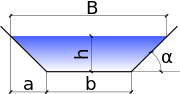
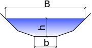
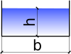
The major characteristics of a canal are the form and size of its section, namely the flow area. The canal may have various forms. Often, trapezoidal and polygonal-shape canals are used. Also, its section may have rectangular, semicircular or parabolic form, delineated by a more compound curve or component.
|
Canal sections |
|||
Trapezoidal |
Polygonal |
Rectangular |
Semicircular |
|
|
|

|
The ratio of slope m given by
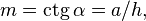
depends on the ground which the canal lies on. While for rocky ground, the ratio of slope approximates to zero, for pulverescent sand, for example, it may come to 3-3.5. Slope paving (soling) will allow setting a required value.
Depending on natural channels, it possible to make a hydraulically optimal size of the canal section (that is to pick up appropriate values, counterparts, of the canal width at the bottom and of the flow depth). With such section at given channel roughness, maximum delivery capacity at minimum section area will be provided. However, for the range of the most usual ratio of slope it turns out that such canals have deep depth and narrow width of the bottom, which is often unreasonable in terms of the practice of the organization and cost of works. In addition to that the flow erosive velocity rises. Therefore, the bottom width of canals is extended in comparison with the hydraulically optimal that.
Estimation of canal capacity
In the general case, small canals’ capacity is calculated under the assumption of uniform motion of water. To determine flow velocity and rate, the Shezi formula is used:
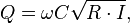
Where
V stands for the average flow velocity, m/s;
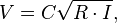
C stands for the coefficient of friction resistance (Shezi coefficient), m0.5/s, representing the integral characteristic of drag forces;
R stands for hydraulic radius, m;
I stands for the hydraulic gradient which at uniform open channel flow is equal to the bottom slope and water surface slope (hydraulic gradient); and
ω stands for cross-sectional wet area, m2.
Canal water discharge is determined through water-management design. The problem consists in the calculation of the canal section and sizes at relatively narrow range of possible flow velocity. The flow velocity range narrowness is due to that the canal bed, on the one hand must, not be eroded and, on the other hand, must not become silted. Calculation of limiting velocity taking into account silting and erosion factors is a complex problem and is solved by approximate methods. For the majority of materials, the eroding velocity values are determined and are given in corresponding tables depending on hydraulic depth.
